With
Tornado side-lined at the National Railway Museum during the winter and little prospect of any work until the spring we have taken the opportunity to change five locomotive driving wheel springs. As previously reported, we changed one driving wheel spring which had broken just before ‘The Ticket to Ride’, and during further inspection we identified two other springs which were starting to show signs distress. After discussions it was decided that the time was now right not only to change the two other distressed springs but to change all the five remaining springs, this would then build in a degree of reliability going forward over the next 12 months. All photos by Richard Pearson.
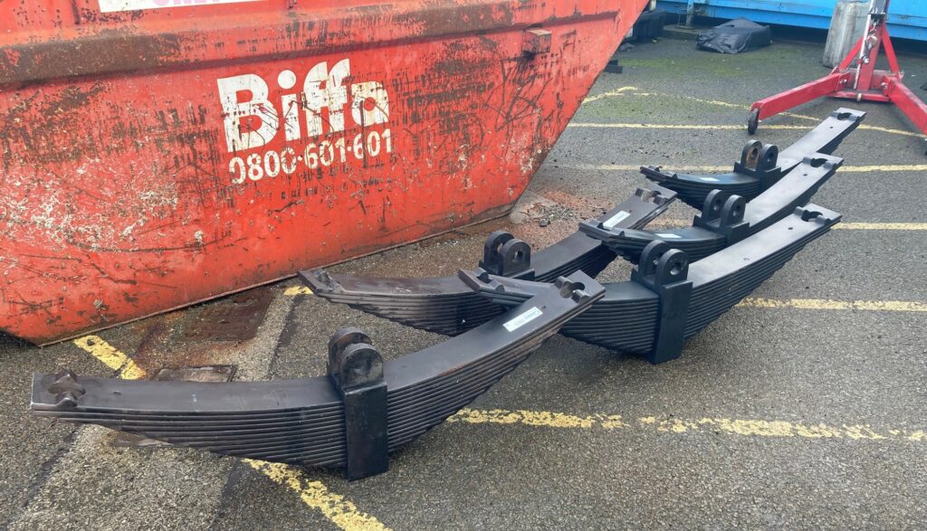
Five new springs before fitting. The springs are very heavy – two people are needed to lift and manoeuvre a spring. Changing a spring is heavy work, with lifting equipment required for removing the old and fitting the new.
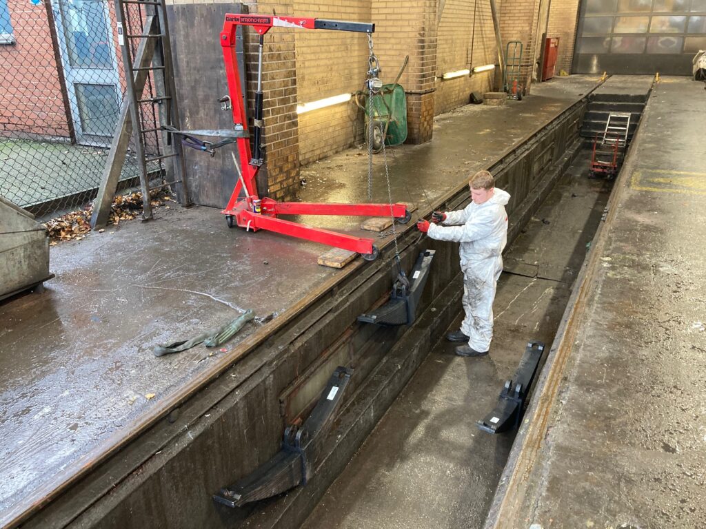
Using the lifting equipment and a lifting block the new springs are carefully lowered into the pit.
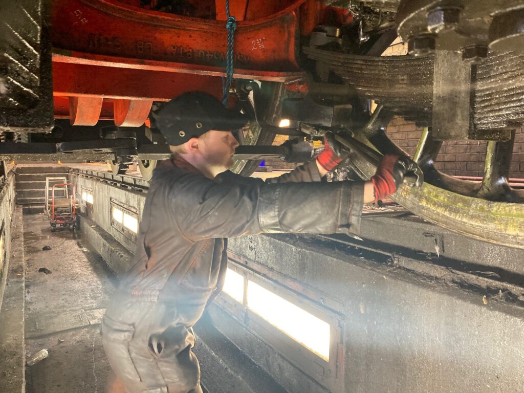
The brake gear pull rods were first removed to create the room we needed under the engine to work. Using the hydraulic jacks, the locomotive is lifted to remove the weight from the springs, and after carefully measuring the position of each nut (so they are refitted back to the original position) they were removed. The photo shows Ian Greenan removing the nuts using the ‘big’ spanner.
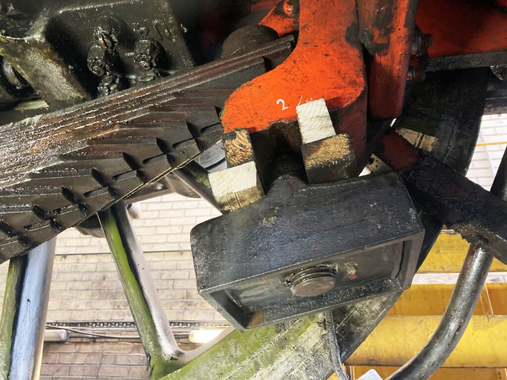
Once the nuts have been removed, the spring boxes should slide off, but unfortunately most were stuck fast on the spring hanger bolts. Releasing the spring boxes proved to be the most difficult and heavy-going part of the job as we had to employ several different techniques to release them. Several sand pipe brackets had to be removed and we also had to be creative in other ways to jack and push off the boxes. The picture shows one of the boxes packed with wood. We then carefully lowered the engine down and used the weight of the engine to push off the box.
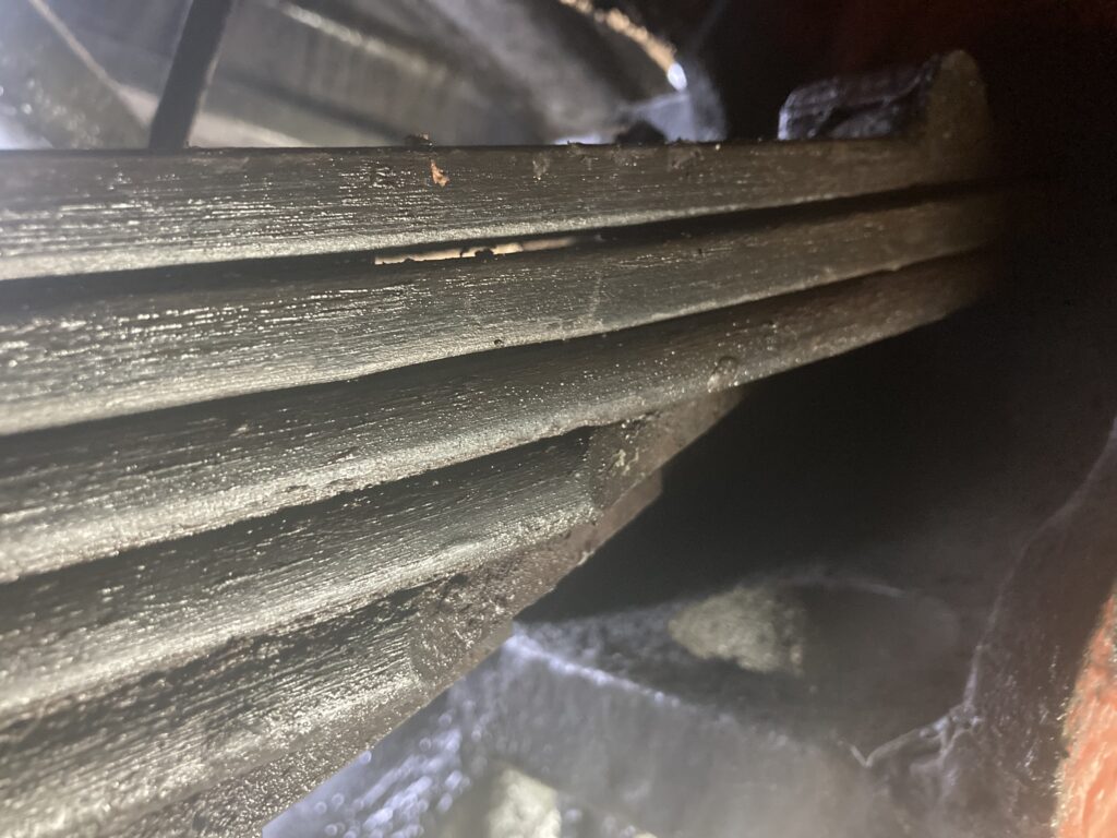
The distress in the old springs is very difficult to show in a photograph, but in this picture you can see that a gap developed between the top and the second leaf, and the shadow at the far end between the top and second leaf shows the offset/twist that has occurred between the leaves. You can also see that there is no offset between the second and third leaves.
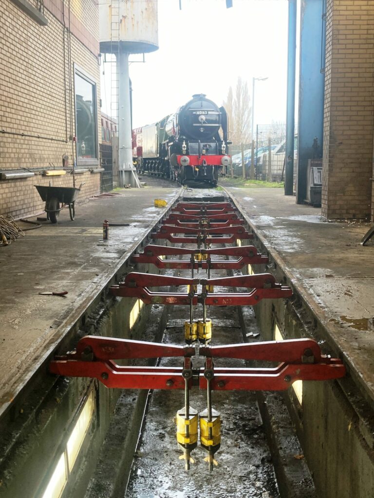
On Monday 23
rd November the NYMR sent a fitter and their weighing equipment to York to allow us to weigh the engine. This process allows you to measure the weight on each wheel and then adjust the tension on each spring to ensure the correct weight distribution is achieved, the picture below shows the weigh beams being set up on the pit.
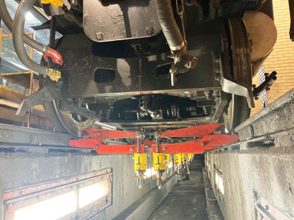
The picture shows the engine sitting on the weighing equipment. Tension is applied to the screws on the bottom of the yellow load cells, this via the lever arm then lifts (floats) the engine off the rails, once lifted the load is measured by the load cells and displayed on the digital display boxes.
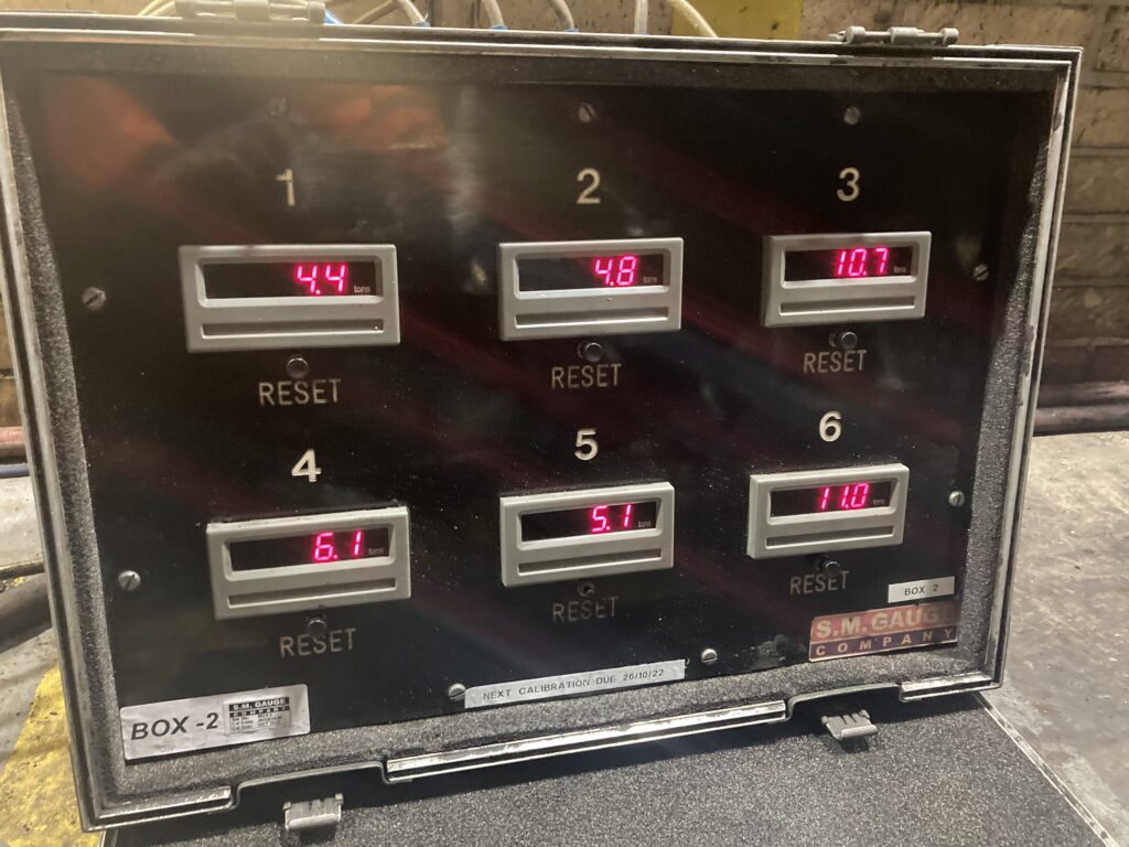
A number of adjustments were made to the driving wheel springs, and after each adjustment the wheels are re-floated and the weights checked. This process took a full day and at the end of the day the readings on the driving wheels and the cartazzi were within spec, but as you can see in the picture above the readings for the leading bogie wheels (1 is front right and 4 front left) were still a long way off.
To bring the weights on the leading bogie wheelset within spec we tried to adjust the bogie spring tensions but, unfortunately, we found the nuts on the spring hanger bolts had seized solid. So, the following day with the help of an oxy/propane heating torch we were able to fully dismantle the front bogie wheel suspension. The spring hanger bolts were cleaned up, and where necessary the threads were dressed and the rubber damper blocks on each bolt were replaced. Everything was then re-assembled and the engine re-weighed, and this time the weights were all within spec.
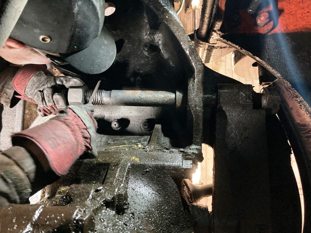
The picture shows Ian dressing one of the bolts.
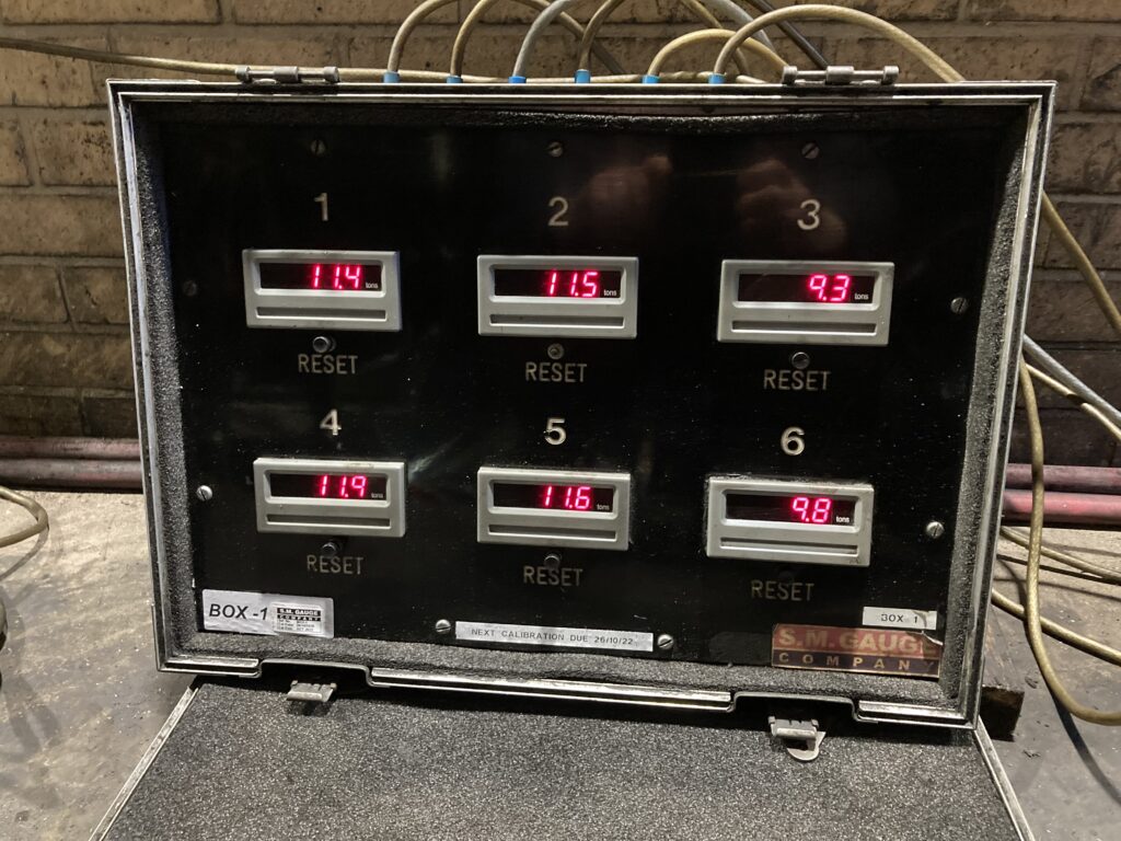
This picture shows the final weights, starting on the left with the front of the engine and working across to the rear on the right, the top row shows the RHS of the engine and the bottom row is the LHS.